Fire Hydrant Valves / Landing Valves
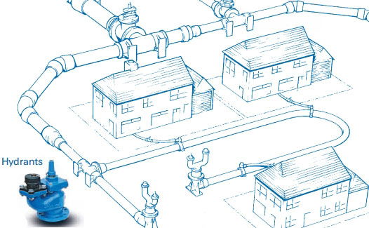
A fire hydrant system comprises water supply pipework and valves to which brigades can connect their hose for fire fighting purposes. They are found almost every for example under public roads, in large buildings, in Tunnels, on Chemical plants, onshore and offshore platforms, on board ships etc. The designs of Fire Hydrant valves and Landing valves are very similar irrespective of the place where they are being installed. They are designed to be robust, not freeze in harsh environments, and operate in a fire in accordance with fire testing regulations. Some also include a reducing valve to regulate the outlet pressure with a varying inlet pressure which is required in some installations. There are also various outlet connections available and special marine approvals. In the U.K. the pressurised mains laid under public roads which distribute water to consumers are also used by fire brigades. Underground hydrant valves to BS 750 are permanently connected to the mains at intervals. Fire hose is connected to the valves via a standpipe.

Tall buildings and structures should have a permanently installed rising main which consists of a vertical pipe with brigade connections to BS 5041 at different levels of the building. There are two types of rising main:
1. Dry Riser This is normally dry but is capable of being charged with water by pumping from a fire service appliance via an inlet breeching fitted on the outside of the building at ground level. An air release valve is fitted at the highest point to enable the riser to be fully charged. There are fire hydrant valves on each floor so that the brigade can connect into the water supply at any level of the building.
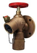
2. Wet Riser A wet riser is a pipe kept permanently charged with water which is then immediately available for use on any floor at which a fire hydrant globe valve (also known as a landing valve) is provided. Wet risers are necessary for buildings (and structure) which are too high for brigade pumps to supply the necessary water pressure via a dry riser. If the mains pressure is higher than maximum brigade operating pressure it is necessary to use pressure regulating landing valves.
 Example Landing Valves (No-built-in regulator / BS336 Instantaneous Female Coupling)
  Broady Hydrant Reducing Valve (With built-in Pressure Regulator / BS336 Instantaneous Female Coupling)
 BS336 Instantaneous fire hose couplings (also known as Morris couplings), are the standard low pressure fire hose fitting for UK fire brigades. They have a male and a female end and are a push fit. Max Working Pressure 15 Bar.
Storz Coupling: This coupling type was originally patented in Switzerland but is now widely used in the US and Europe. Benefit of this connection type is that every end is identical and can be joined to any other end of the same diameter. To couple a Storz connection, the two opposing couplings are pressed together such that the hooks of each one are inserted into the slots in the flange of the other. Then they are rotated in opposite directions until they are tight, or latches engage. Many other coupling designs are based around this design. Working pressure 16 bar.
NOR Coupling: Symmetric coupling (Storz type) designed according to Norwegian standard. Working pressure 10 bar.
ROTTA Coupling: Symmetric coupling (Storz type) designed according to Russian ROTTA ROTH standard. Working pressure 10 bar.
For further help or information about these products please contact us on +44 (0)1482 601030 or email
sales@flowstar.co.uk.